Why Jumbo Rolls? – The Economics of Scale in Tape Manufacturing
In high-volume electronics manufacturing, every second of downtime and every square millimeter of waste translates directly to cost. This is why the format in which shielding tape is supplied — standard rolls versus jumbo rolls — is not a trivial logistical detail but a strategic supply chain decision. Jumbo rolls represent an industrial-scale approach to tape delivery, designed specifically for automated, continuous, and high-efficiency production environments.
This section defines what jumbo rolls are, quantifies their operational and economic advantages, and provides a framework for determining when a jumbo roll configuration makes sense for your manufacturing line.
1. What Is a Jumbo Roll?
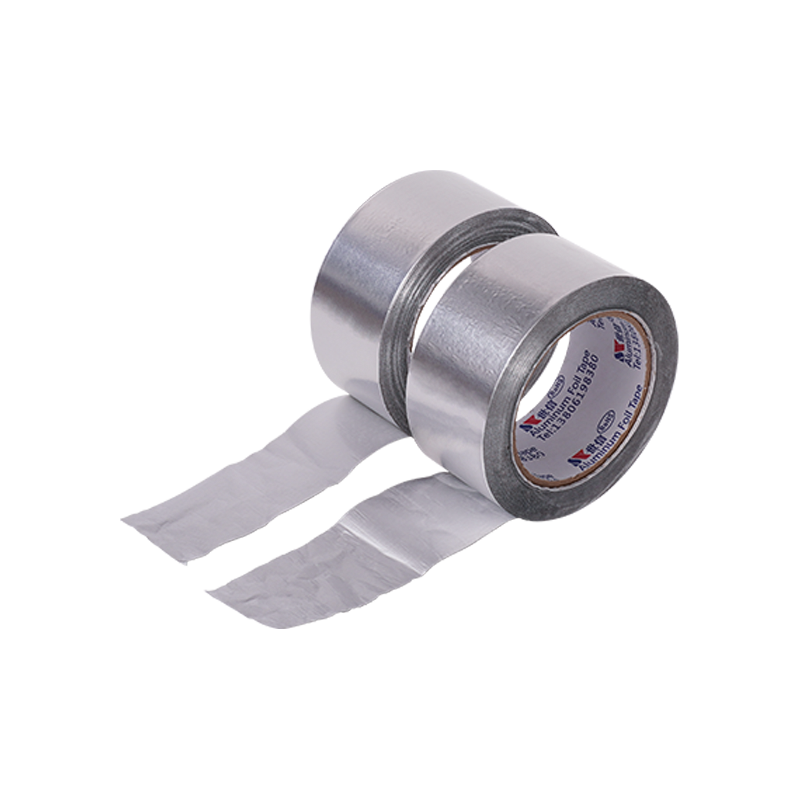
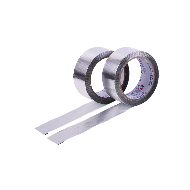
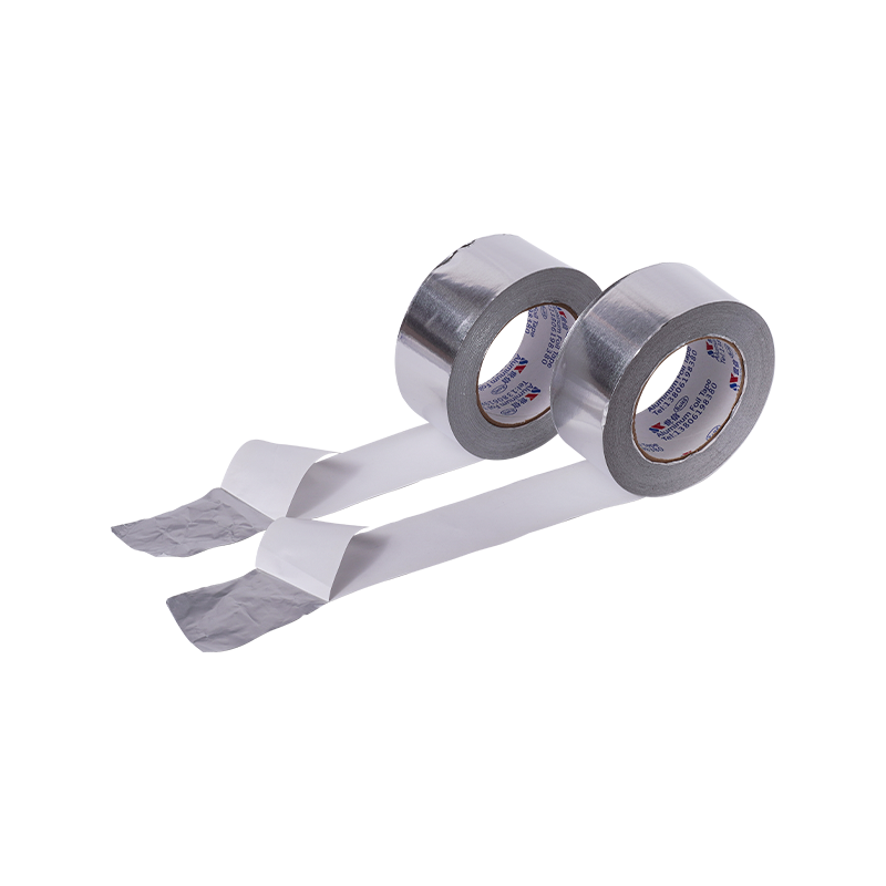
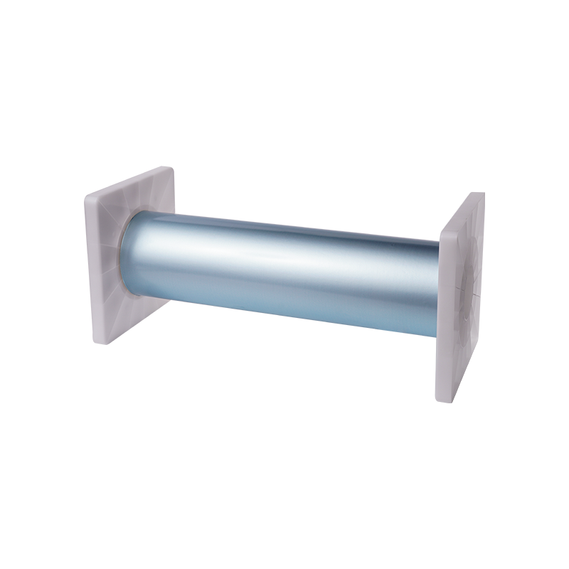
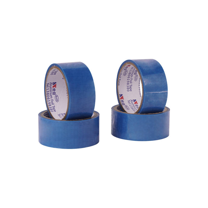
A jumbo roll is a large-format roll of tape — typically produced directly from the coating and converting line — with dimensions substantially larger than standard retail or job-shop rolls. While there is no universal standard, jumbo rolls in the context of foil tapes are generally characterized by:
- Width:500 mm to 1,500 mm (approximately 20 to 60 inches), though widths up to 1,800 mm are available for specialized applications.
- Length:500 meters to 1,000 meters or more per roll, depending on foil thickness and adhesive coating weight.
- Core diameter:Typically 3 inches (76.2 mm) or 6 inches (152.4 mm) to accommodate heavy-duty unwind stands.
- Weight:Can range from 50 kg to over 300 kg per roll, requiring mechanical handling equipment.
Jumbo rolls are not intended for manual application. They are designed for roll-to-roll processing, automated lamination, high-speed slitting operations, or large-format die-cutting lines.
2. The Economics of Scale — Why Size Matters
The transition from standard rolls to jumbo rolls affects costs across multiple dimensions — material, labor, process, and logistics. The compounding effect of these savings makes jumbo rolls significantly more cost-efficient on a per-unit-area basis.
Direct Material Cost Savings:
- Bulk purchasing of jumbo rolls reduces the manufacturer's per-meter production cost — fewer changeovers on the coating line, less startup waste, and more efficient use of coating and drying equipment.
- These savings are typically passed on to the customer as a 10–20% lower cost per square metercompared to standard roll equivalents.
Reduced Changeover Downtime:
- In automated lamination or slitting lines, each roll change requires stopping the line, threading the new roll, and verifying tension and alignment — typically 5–15 minutes per changeover.
- A standard roll (50–200 meters) on a high-speed line running at 10 m/min lasts 5–20 minutes. A jumbo roll (500–1,000 meters) lasts 50–100 minutes — 3 to 5 times longer.
- Over an 8-hour shift, a line using standard rolls may require 4–8 changeovers. With jumbo rolls, that number drops to 1–2, reducing downtime by 30–45 minutes per shift.
Waste Reduction:
- Every roll change leaves residual tape on the core (core waste) and requires a new leader/trailer for threading.
- With fewer rolls per shift, the total waste from cores, leaders, and trims is significantly lower on a per-square-meter basis — typically 2–3% waste for jumbo rollsversus 5–8% for standard rolls.
Logistics and Packaging:
- Fewer rolls to ship means less packaging material (cores, boxes, pallets) per square meter of tape delivered.
- Reduced freight volume and weight — potentially lowering shipping costs by 5–10%depending on destination and mode.
3. Jumbo Roll vs. Standard Roll — Comprehensive Comparison
The table below provides a side-by-side comparison of key operational and economic parameters between standard rolls and jumbo rolls, based on typical values observed in high-volume electronics tape applications.
|
Parameter
|
Standard Roll (Typical)
|
Jumbo Roll (Typical)
|
Benefit / Impact
|
|
Width range
|
10 – 300 mm
|
500 – 1,500 mm
|
Enables slitting to multiple narrower widths from a single jumbo roll, reducing setup time for different product sizes
|
|
Length per roll
|
50 – 200 m
|
500 – 1,000 m
|
3–5× longer run life; 60–80% fewer roll changes
|
|
Roll changes per 8-hour shift
|
4 – 8 changes
|
1 – 2 changes
|
Saves 30–45 minutes of downtime per shift (assuming 5–15 min per changeover)
|
|
Core waste per shift
|
4–8 cores discarded
|
1–2 cores discarded
|
Reduces material waste by 60–75% on cores and leaders
|
|
Packaging waste (per m²)
|
Higher (individual boxes, labels, wraps)
|
Lower (bulk packaging)
|
Reduced environmental footprint; lower disposal cost
|
|
Cost per m² (relative)
|
Reference baseline (higher)
|
10 – 20% lower
|
Direct material cost reduction from bulk manufacturing efficiency
|
|
Handling method
|
Manual (single operator)
|
Mechanical (hoist, forklift, shaft lift)
|
Requires investment in handling equipment but improves safety and speed
|
|
Typical unwind stand compatibility
|
Standard shaft or brake stands
|
Heavy-duty shaft stands with core brakes
|
Jumbo rolls require compatible unwinding infrastructure
|
|
Storage footprint (per 1,000 m² of tape)
|
Larger (more rolls, more shelves)
|
Smaller (fewer, larger rolls)
|
Reduced warehouse space requirement
|
4. Operational Impact — Beyond Cost
While cost savings are the most tangible benefit, jumbo rolls also deliver quality and process consistency advantages that are equally important in demanding applications like EMI shielding and thermal management.
Consistent Tension Control:
- Each roll change introduces a risk of tension variation as the new roll is threaded and the control loop re-stabilizes. Tension variation can cause stretch, wrinkling, or misregistration in the applied tape.
- With fewer roll changes, the line runs at stable tension for longer periods, improving the consistency of tape placement, shielding coverage, and adhesive wet-out.
Reduced Splice Risk:
- In continuous lamination processes, the end of one roll must be spliced to the beginning of the next. Splices create non-uniform thickness and are potential failure points in the final product.
- Jumbo rolls reduce the number of splices requiredover a given production run by a factor of 3–5, directly improving product reliability.
Simplified Inventory Management:
- Managing fewer, larger rolls simplifies stock tracking, reduces the number of SKUs to monitor, and lowers the administrative overhead of inventory control.
- A single jumbo roll can often supply multiple product lines after slitting, further consolidating raw material SKUs.
5. When Should You Consider Jumbo Rolls?
Not every application is suited for jumbo rolls. The decision should be based on a combination of volume, line speed, available infrastructure, and product diversity. The following guidelines can help determine suitability:
- High-volume, continuous production:If your line runs more than 4 hours per day with the same tape width, jumbo rolls are almost certainly cost-effective.
- Multiple width requirements:If you slit tape to various widths from a master roll, jumbo rolls provide maximum slitting yield and minimize trim waste.
- Automated application equipment:Jumbo rolls are designed for machines with heavy-duty unwind stands — if you have the infrastructure, the operational savings are immediate.
- Long production runs of a single SKU:For products like automotive wire harnesses or large-format display backplanes, where the same tape is used continuously for hours at a time, jumbo rolls are ideal.
When jumbo rolls may not be suitable:
- Low-volume or prototyping environments:The minimum order quantity for jumbo rolls is typically higher; standard rolls may be more practical for R&D or low-mix production.
- Limited handling infrastructure:If your facility lacks hoists, forklifts, or heavy-duty unwind stands, the physical weight of jumbo rolls may be impractical.
- Frequent product changes:If you change tape types or widths multiple times per shift, the advantage of longer run lengths diminishes.
6. Transition Planning — Moving to Jumbo Rolls
Shifting from standard rolls to jumbo rolls requires some planning to ensure a smooth transition:
- Infrastructure audit:Confirm that your unwind stands can accept the larger core and weight. Consider shaft adapters if core diameters differ.
- Slitting capability:If you are purchasing wide jumbo rolls and slitting in-house, ensure your slitting equipment can handle the full width and weight.
- Storage:Allocate racking that can support heavy rolls (up to 300 kg) and provide easy access for material handling equipment.
- Supplier qualification:Ensure your tape supplier can consistently deliver jumbo rolls with the same quality, flatness, and adhesion properties as standard rolls — any variation in the larger format is magnified in automated lines.
- Pilot run:Before committing to full-scale conversion, run a pilot batch using jumbo rolls to validate tension, splicing, and changeover procedures on your specific equipment.
Summary — The Value Proposition of Jumbo Rolls
The move to jumbo rolls is not merely about buying tape in bulk — it is a strategic alignment of supply chain with production process. The cumulative benefits — lower material cost, reduced downtime, less waste, consistent tension, and simplified inventory — create a compelling value proposition for high-volume manufacturers. In the context of custom-size water-base linerless foil tape, jumbo rolls amplify the advantages of water-based adhesives and custom dimensions, delivering a complete solution for modern, sustainability-conscious electronics production.
The Water-Base Adhesive Advantage – Environmental & Performance Dimensions
The adhesive system is the "intelligence" of any tape. It determines how well the tape bonds to substrates, how reliably it conducts or insulates, and how long it performs under environmental stress. In the context of custom-size linerless foil tape, the choice between water-base (aqueous) and solvent-base adhesive systems is particularly consequential — influencing not only adhesion performance but also regulatory compliance, manufacturing safety, and end-of-life sustainability.
This section examines water-base adhesives from the perspectives of chemistry, environmental impact, performance characteristics, and application compatibility, providing engineers and procurement professionals with the data needed to make an informed selection.
1. What Is a Water-Base Adhesive?
A water-base adhesive — also referred to as an aqueous adhesive or waterborne adhesive — uses water as the primary carrier or solvent for the polymer resin, rather than organic solvents such as toluene, acetone, or methyl ethyl ketone (MEK). The polymer components (typically acrylic, butyl rubber, or hybrid chemistries) are dispersed or emulsified in water, often with surfactants, stabilizers, and cross-linking agents.
Key structural components:
- Polymer emulsion:The active adhesive material, typically 40–60% solids by weight.
- Water carrier:The medium that allows the adhesive to be coated and dried; evaporates during the manufacturing process.
- Coalescing agents:Small amounts of high-boiling solvents (typically <5% VOC) that assist film formation during drying.
- Cross-linkers:Functional additives that react during curing to build cohesive strength and heat resistance.
- Surfactants and wetting agents:Ensure uniform coating on the foil substrate.
During production, the water-based emulsion is coated onto the foil and passed through a drying oven where the water and minor coalescing agents are evaporated, leaving a solid, tacky adhesive film ready for contact.
2. Environmental and Regulatory Advantages
The primary driver for the adoption of water-base adhesives in recent years has been regulatory compliance and environmental responsibility. Solvent-base adhesives, while offering excellent performance, carry significant environmental and safety burdens.
Volatile Organic Compounds (VOCs):
- Water-base adhesives typically contain <5 g/L of VOCs(by coating weight). Solvent-base adhesives often range from 200 to 600 g/L or higher.
- This difference has direct regulatory implications: many jurisdictions (EPA in the US, REACH in Europe, and GB standards in China) impose strict VOC limits on manufacturing facilities. Water-base adhesives allow manufacturers to operate within compliance limitswithout expensive abatement equipment like thermal oxidizers.
Flammability and Workplace Safety:
- Water-base adhesives are non-flammableand do not require explosion-proof handling systems, special storage cabinets, or hazardous material transport classification.
- Solvent-base adhesives are flammable liquids, requiring NEC Class I, Division 1 or 2electrical ratings in production areas, specialized fire suppression, and trained handling procedures.
- The elimination of these requirements reduces both capital investment(in facility infrastructure) and operating expenses (insurance, safety training, waste disposal).
Waste Disposal and End-of-Life:
- Solvent-base adhesive residues are classified as hazardous waste, requiring specialized disposal and increasing manufacturing cost.
- Water-base residues are non-hazardousin most jurisdictions, simplifying waste management and reducing disposal fees by 30–60%.
- From a product lifecycle perspective, aluminum foil with water-base adhesive is more easily recycled than foil with solvent-based systems, as the adhesive can be more effectively removed in pyrolytic recycling processes.
3. Performance Characteristics — How Water-Base Adhesives Compare
There is a common misconception that water-base adhesives are inherently "weaker" than solvent-base systems. In reality, modern water-base formulations meet or exceed solvent-base performance in most electronics tape applications, particularly when properly formulated and cured.
Peel Adhesion (Bond Strength):
- Water-base acrylics on stainless steel typically achieve ≥10 N/in(90° peel, ASTM D3330) — comparable to solvent-base systems in the same polymer family.
- On low-surface-energy substrates (plastics like PP, PE), water-base adhesives benefit from carefully balanced surfactants that improve wet-out, often achieving equal or better adhesionto solvent systems.
Shear Strength (Cohesive Resistance):
- Cross-linked water-base acrylics exhibit ≥500 minutesshear retention at 70°C with a 500g load (ASTM D3654).
- High-performance water-base systems can exceed 1,000 minutes, matching the top tier of solvent-base products.
Moisture and Humidity Resistance:
- Water-base adhesives, when formulated with hydrophobic monomers and proper cross-linking, provide excellent moisture resistance— often superior to solvent-base systems because the surfactant package can be engineered to minimize water absorption.
- Typical WVTR through a 0.025 mm adhesive layer is <0.5 g/m²·dayat 38°C/90% RH, comparable to or better than solvent systems.
Temperature Resistance:
- Water-base acrylics typically support continuous operation from −40°C to +120°C.
- Solvent-base systems may extend to 150°C in specialized formulations, but the gap has narrowed significantly with advanced water-base cross-linking chemistries. For most electronics and automotive applications, 120°C is more than adequate.
4. Water-Base vs. Solvent-Base Adhesives — Comparative Summary
The table below provides a side-by-side comparison of water-base and solvent-base adhesives across environmental, safety, and performance dimensions.
|
Attribute
|
Water-Base Adhesive
|
Solvent-Base Adhesive
|
Why Water-Base Is Preferred
|
|
VOC content
|
<5 g/L
|
200 – 600 g/L
|
Meets strict global emissions regulations; no abatement equipment required
|
|
Flammability
|
Non-flammable
|
Flammable (Flash point typically -20°C to 40°C)
|
Safer handling; lower insurance premiums; less facility infrastructure
|
|
Hazardous waste classification
|
Non-hazardous (in most regions)
|
Hazardous (requires specialized disposal)
|
Lower disposal costs by 30–60%
|
|
Initial tack (quick stick)
|
Good to excellent
|
Excellent
|
Comparable for most substrates; can be enhanced with tackifiers
|
|
Peel adhesion (SS, 90°)
|
≥10 N/in
|
≥10 N/in
|
Equivalent performance in electronics applications
|
|
Shear strength (70°C, 500g)
|
≥500 min (cross-linked)
|
≥500 min
|
Comparable; high-performance variants >1,000 min
|
|
Moisture/water resistance
|
Good to excellent
|
Moderate to good
|
Water-base systems often engineered for lower WVTR
|
|
Continuous temperature limit
|
−40°C to +120°C
|
−40°C to +150°C
|
Sufficient for 95% of electronics applications; high-temp water-base variants available
|
|
Coating line safety requirements
|
Standard ventilation
|
Explosion-proof equipment, gas monitoring, fire suppression
|
Much lower capital investment
|
|
Carbon footprint (manufacturing)
|
Lower (less energy for drying)
|
Higher (energy-intensive solvent recovery)
|
Aligns with corporate sustainability goals
|
|
Drying speed (line speed)
|
Moderate (water requires more energy to evaporate)
|
Fast (solvents evaporate more readily)
|
May require longer ovens; trade-off against environmental benefits
|
5. Application Compatibility — Where Water-Base Adhesives Excel
Beyond the environmental and performance profile, water-base adhesives offer specific application advantages that make them particularly suitable for custom-size linerless foil tape.
Compatibility with Linerless Tape Construction:
- Water-base adhesives can be coated directly onto the foil backside release coatingwithout interacting with the silicone release system.
- The absence of aggressive solvents prevents damage to the foil substrate's passivation layer— important for corrosion resistance and long-term electrical contact.
Adhesion to Sensitive Substrates:
- Water-base acrylics are known for low acid content and minimal corrosive interactionwith copper, aluminum, and silver-plated surfaces.
- This makes them particularly well-suited for direct contact with PCB traces, antenna ground planes, and sensor electrodeswhere ionic contamination must be strictly controlled.
Low Odor and Outgassing:
- Residual solvent levels in water-base adhesives are effectively zero after drying. This minimizes outgassing in enclosed electronicsand reduces risk of fogging on optical components or condensation on sensor surfaces.
- For aerospace and medical applications, this is often a mandatory attribute(e.g., NASA low-outgassing standards).
6. Limitations and Mitigations
While water-base adhesives are highly capable, they do have some inherent limitations compared to solvent-base systems. However, modern formulation technology addresses most of these effectively.
- Drying speed:Water requires more energy to evaporate than organic solvents, so coating lines may need longer ovens or elevated temperatures. Mitigation: High-velocity air impingement ovens and infrared pre-heaters optimize drying efficiency.
- Water sensitivity during storage:Improperly stored water-base rolls can absorb ambient moisture, affecting performance. Mitigation: Moisture-barrier packaging and controlled storage conditions (40–60% RH).
- Higher minimum coat weight:Water-base emulsions cannot be coated as thinly as solvent systems without risking pinholes. Mitigation: Advanced precision coating technology can achieve adhesive layers down to 15–20 microns with defect-free coverage.
In the context of linerless foil tape for EMI and heat shielding, these limitations are well-managed in modern manufacturing and do not compromise the overall performance advantage of the water-base adhesive platform.
7. Selection Criteria — Choosing Water-Base for Your Application
When specifying a water-base adhesive for custom-size linerless foil tape, engineers should consider the following factors:
- Substrate type:Does the adhesive need to bond to metals (aluminum, copper), plastics (PC, ABS, FR4), or glass? Water-base acrylics offer broad compatibility; butyl systems are preferred for high-moisture environments.
- Operating temperature range:For ambient to 105°C, standard water-base acrylic is sufficient. For 105–120°C, select a cross-linked variant. Above 120°C, consult the supplier for high-temp modifications.
- Humidity exposure:If the tape will be exposed to high humidity or direct water contact, ensure the water-base adhesive is formulated with hydrophobic monomers and adequate cross-linking density.
- Regulatory requirements:Confirm that the adhesive meets the specific VOC, RoHS, REACH, and any industry-specific (e.g., aerospace, automotive) compliance standards for your region.
- Production line compatibility:Verify that your coating, drying, or lamination process can handle the drying requirements of water-base adhesives.
Summary — The Strategic Advantage of Water-Base Adhesives
Water-base adhesives are not merely "greener" than solvent-base alternatives — they are technically competitive and operationally advantageous across the full spectrum of EMI and heat shielding applications. Their low VOC profile, non-flammability, lower disposal costs, and excellent adhesion performance make them the preferred choice for modern, sustainability-conscious manufacturing environments. When combined with linerless foil construction and custom jumbo roll sizing, the water-base adhesive system completes a holistic solution that addresses performance, compliance, and cost in equal measure.
"Custom-Size" – The Flexibility Dimension
In the context of industrial tape supply, "custom-size" is more than a convenience — it is a strategic capability that directly impacts production efficiency, material utilization, and product quality. When applied to water-base linerless foil tape in jumbo roll format, custom-sizing transforms a commodity material into a production-optimized solution tailored to the specific geometry, volume, and process requirements of the end user.
This section defines the scope of custom-size parameters, explains how customization creates tangible value across different manufacturing environments, and provides decision criteria for specifying the optimal configuration.
1. What Does "Custom-Size" Mean?
Unlike standard off-the-shelf products that are offered in fixed widths, lengths, and core sizes, custom-size tape is manufactured to customer-defined specifications — typically with minimum order quantities that vary by the complexity of the customization. The key parameters that can be customized include:
- Width:From 10 mm to 1,500 mm or wider, in 1 mm or 5 mm increments.
- Length:From 100 meters to 1,000 meters or more per roll, depending on thickness and core capacity.
- Core diameter:Standard 3 inches (76.2 mm), 6 inches (152.4 mm), or custom diameters (e.g., 2 inches, 4 inches) to fit specific unwind shafts.
- Foil thickness:Typically 0.025 mm, 0.035 mm, 0.050 mm, or 0.080 mm, selected based on shielding and flexibility requirements.
- Adhesive coating weight:Expressed in grams per square meter (g/m²) or dry film thickness, ranging from 15 to 40 microns.
- Release coating type and thickness:The silicone release layer on the foil backside can be adjusted for different unwind force requirements.
- Slitting tolerance:Precision slitting to ±0.5 mm or tighter, depending on application requirements.
Some suppliers also offer custom slitting patterns — for example, a single jumbo roll slit into multiple widths (e.g., three widths of 100 mm, 75 mm, and 50 mm) all on the same core, or multiple narrow rolls nested on a single jumbo core.
2. The Value of Customization — Quantifying the Benefits
Customization delivers value across four primary dimensions: material efficiency, process efficiency, quality, and supply chain simplification.
Material Efficiency (Reduced Waste):
- When tape is purchased at a standard width and slit in-house, the difference between the standard width and the required width becomes trim scrap. For example, purchasing a 500 mm roll to slit into 450 mm finished width generates 10% waste (50 mm trim).
- With custom sizing, the tape is delivered at the exact width required— eliminating trim waste entirely. In high-volume applications, this can save 5–15% of total material consumption.
- Length customization similarly reduces waste — if a standard roll length is 200 m but your production run requires 150 m, the remaining 50 m may sit on the shelf or become remnant scrap. Custom length ensures each roll is consumed completely.
Process Efficiency (Reduced Setup and Downtime):
- Receiving tape at the exact required width eliminates the need for in-house slitting operations, reducing machine setup time, labor, and capital equipment requirements.
- When tape arrives at precisely the right width, line adjustments are minimized— the tape feeds directly into the applicator, laminator, or winding machine without additional conversion steps.
- Consistent roll dimensions (width, length, core size) mean that equipment parameters such as web guides, tension controls, and splice detectors can be set once and remain stableacross entire batches.
Quality Improvement:
- In-house slitting can introduce defects: burrs on slit edges, dust contamination, or inconsistent edge straightness. Custom slitting performed in a controlled, cleanroom-compatible environment by the tape manufacturer typically achieves higher edge quality and dimensional consistency.
- Precision width tolerance (±0.5 mm or better) ensures that the tape fits perfectly into designed channels or slots, eliminating gaps or overlapthat could compromise EMI shielding or sealing.
Supply Chain Simplification:
- Custom-sizing reduces the number of SKUs required to support multiple product lines. Instead of stocking multiple standard widths, a single custom-slit jumbo roll can supply all required widths in one order.
- Longer custom lengths reduce order frequency — fewer purchase orders, fewer deliveries, and lower administrative overhead.
3. Customization Parameters — Typical Ranges and Tolerances
The table below summarizes the typical customization parameters available for water-base linerless foil tape, along with recommended tolerance ranges and factors to consider when specifying each parameter.
|
Parameter
|
Typical Range
|
Common Tolerances
|
Considerations
|
|
Width
|
10 – 1,500 mm
|
±0.5 mm (precision); ±1.0 mm (standard)
|
Narrower widths (<20 mm) may have edge curl risks; wider widths (>1,200 mm) require heavier handling equipment
|
|
Length
|
100 – 1,000 m
|
±2% of total length
|
Longer rolls reduce changeovers but increase roll weight; balance against handling capacity
|
|
Core diameter
|
3" (76.2 mm), 6" (152.4 mm), or custom
|
±0.5 mm
|
Ensure compatibility with existing unwind shafts and chucks; core strength must support roll weight
|
|
Foil thickness
|
0.025 – 0.080 mm
|
±0.003 mm
|
Thinner foils offer better conformability; thicker foils provide higher shielding and thermal mass
|
|
Adhesive coat weight
|
15 – 40 g/m² (dry)
|
±5% of target
|
Higher coat weight improves adhesion but increases thickness and cost; lower coat weight reduces thickness but may compromise bonding on rough surfaces
|
|
Release coating weight
|
0.5 – 2.0 g/m²
|
±0.2 g/m²
|
Higher release coating reduces unwind force but may transfer silicone onto the adhesive, affecting conductivity
|
|
Slitting pattern
|
Single width, multi-width (nested), or master roll only
|
N/A (defined per order)
|
Multi-width slitting can reduce per-roll packaging waste but requires careful planning of width combinations
|
4. Customer Segments and Their Customization Drivers
Different types of tape users have distinct customization priorities. The table below maps common customer segments to their primary customization drivers and typical custom-size configurations.
|
Customer Segment
|
Primary Customization Driver
|
Typical Configuration
|
Why This Configuration?
|
|
Automotive wire harness manufacturers
|
Multiple narrow widths for cable wrapping
|
Jumbo roll (1,200 mm) slit to 10–50 mm widths, 500–1,000 m lengths, 3" core
|
One jumbo roll supplies several harness lines; reduces changeovers and floor space for roll storage
|
|
EMI gasket and die-cut component producers
|
Just-in-time (JIT) supply with specific die-fit dimensions
|
Custom width matching die layout (e.g., 150 mm, 225 mm), lengths determined by monthly consumption
|
Eliminates secondary slitting; tape feeds directly into die-cut presses with minimal handling
|
|
Large-format display panel manufacturers
|
Maximizing material yield for large panel areas
|
Very wide jumbo rolls (1,300–1,500 mm) at full width, with customized core to fit panel lamination equipment
|
Minimizes seams and overlaps in large-area EMI shielding; reduces overall tape usage per panel
|
|
5G antenna enclosure assemblers
|
Precision width for automated pick-and-place lamination
|
Narrow precision-width rolls (e.g., 25 mm, 50 mm) with tight ±0.3 mm tolerance, 500 m+ length
|
Prevents misplacement in automated lines; reduces splice frequency in continuous lamination
|
|
Aerospace and defense manufacturers
|
Lot traceability and batch consistency
|
Custom length per batch (e.g., 200 m) with specific foil and adhesive thickness, strict tolerance, individual roll labeling
|
Ensures full traceability and reduces variability across production batches
|
5. Customization Decision Framework — How to Specify Your Tape
When specifying a custom-size water-base linerless foil tape, we recommend the following step-by-step approach to ensure the configuration optimally balances performance, cost, and operational efficiency.
Step 1 – Define your required finished width:
- Measure the width required for your final application — whether it's the width of a cable wrap, the width of a shielding strip, or the width that matches a die-cut pattern.
- Consider tolerances: if your application allows ±1 mm, a standard tolerance is sufficient; if it requires precise fit (e.g., within a channel), request ±0.5 mm or tighter.
Step 2 – Determine your required length per roll:
- Calculate average daily or weekly consumption of the tape in linear meters.
- Choose a roll length that supports at least one full production shiftto minimize changeovers, but ensure the roll weight remains manageable for your handling equipment.
- As a rule of thumb: roll weight (kg) ≈ width (m) × length (m) × total tape thickness (mm) × foil density (2.7 for Al). For manual handling, keep rolls below 30 kg; for automated handling, up to 300 kg is acceptable.
Step 3 – Select the core diameter:
- If your existing equipment uses 3" chucks, standardize on 3" cores. If you are using shaft-type unwinds, 6" cores provide better stability for heavy jumbo rolls.
- Custom core diameters are possible but may require minimum order quantities and longer lead times — confirm feasibility with your supplier.
Step 4 – Choose foil thickness based on performance requirements:
- 025 mm:Lightweight, high conformability — suitable for curved surfaces and space-constrained electronics.
- 035 mm:Balanced thickness — good general-purpose shielding and thermal spreading.
- 050 mm:Enhanced mechanical strength and shielding — suitable for high-vibration environments.
- 080 mm:Maximum shielding and heat spreading — for demanding industrial and aerospace applications where stiffness is acceptable.
Step 5 – Specify adhesive coat weight:
- For smooth metal substrates, 15–20 g/m² is typically sufficient.
- For rough or textured surfaces (e.g., cast aluminum, FR4, powder-coated metals), 25–35 g/m² is recommended to ensure full wet-out and adequate contact area.
- Higher coat weights (35+ g/m²) may be needed for high-peel-strength requirements or applications requiring gap-filling.
Step 6 – Consider multi-width slitting for maximum efficiency:
- If your facility uses multiple tape widths, consider ordering a jumbo roll slit into a combination of widths. For example, a 1,200 mm roll slit into 4 × 100 mm + 6 × 50 mm + waste trim.
- Multi-width slitting reduces the total number of jumbo rolls required and can lower overall per-meter cost by 5–8%.
6. Case Example — Custom Sizing in Practice
Scenario: A manufacturer of automotive battery management systems (BMS) uses a water-base linerless foil tape to shield and ground flex circuits in a battery pack. The current process uses standard 300 mm wide rolls, which are manually slit in-house to 25 mm widths for cable wrapping and 75 mm widths for module shielding. The in-house slitting process produces 15% trim waste, requires 2 hours of setup per week, and generates edge-quality issues that cause intermittent grounding failures.
Custom-Size Solution: The manufacturer transitions to a custom jumbo roll configuration:
- One 1,200 mm wide jumbo roll, slit by the manufacturer into: 8 rolls of 75 mm width and 12 rolls of 25 mm width.
- Length per roll: 500 m.
- Core: 3" diameter to fit existing unwind stands.
- Foil: 0.035 mm aluminum with water-base acrylic adhesive, 25 g/m² coat weight.
Results achieved:
- Trim waste eliminated— 15% material savings.
- Setup time reducedfrom 2 hours/week to 15 minutes/week (slitting equipment no longer used).
- Edge quality improved— grounding failure rate dropped from 3.2% to 0.9%.
- Inventory consolidation— 3 SKUs replaced by 1 SKU (the jumbo roll with specified slitting pattern).
Summary — The Strategic Value of Custom Sizing
Custom-sizing of water-base linerless foil tape in jumbo roll format is not merely a logistical convenience — it is a competitive advantage for manufacturers seeking to reduce waste, improve process efficiency, and enhance product quality. By specifying exactly the width, length, core, and slitting pattern required, users can eliminate secondary conversion steps, reduce material consumption, and ensure consistent tape performance at every stage of production. The combination of custom-size capability with water-base adhesive chemistry and jumbo roll format represents a complete, optimized solution for high-volume shielding applications across automotive, telecom, aerospace, and consumer electronics industries.
Technical Performance Profile – Foil + Adhesive System
The performance of any shielding tape is ultimately defined by the synergy between the foil substrate and the adhesive system. In the case of custom-size water-base linerless foil tape, this synergy is particularly important because the tape is expected to fulfill multiple functions simultaneously: EMI shielding, thermal management, moisture sealing, and reliable mechanical attachment — all within a single, thin layer.
This section provides a comprehensive technical profile of the combined foil-and-adhesive system, including quantifiable performance metrics across electrical, thermal, mechanical, and environmental domains. All values are derived from standardized test methods and represent typical performance under controlled laboratory conditions.
1. EMI Shielding Performance
The primary function of the foil layer is to provide a continuous conductive barrier against electromagnetic interference. The shielding effectiveness (SE) of the tape is determined by the foil material, foil thickness, adhesive conductivity, and the integrity of the bond line.
Shielding Effectiveness (SE):
- Test Method:ASTM D4935 (Standard Test Method for Measuring the Electromagnetic Shielding Effectiveness of Planar Materials).
- Frequency Range:30 MHz to 18 GHz — covering the majority of commercial, automotive, and aerospace communication bands, including 5G (up to 39 GHz with extended testing).
- Typical Value:>70 dB across the full 30 MHz–18 GHz range for 0.035 mm aluminum foil with conductive water-base adhesive.
- Interpretation:70 dB attenuation corresponds to a reduction of incident electromagnetic energy by a factor of 10,000,000 — sufficient for most FCC Part 15 Class B, CISPR 25, and MIL-STD-461 requirements.
Factors Affecting SE:
- Foil thickness:Thicker foils provide higher SE, particularly at lower frequencies where skin depth is greater. Increasing from 0.025 mm to 0.080 mm typically improves SE by 5–10 dB.
- Foil material:Copper provides slightly better SE than aluminum (approximately 3–5 dB advantage) due to higher conductivity, but aluminum is lighter and more cost-effective for most applications.
- Adhesive conductivity:The water-base adhesive is typically formulated with silver-coated copper or nickel particles to ensure electrical continuity across the bond line. A non-conductive adhesive would create a resistive barrier, reducing SE by 20–30 dB.
- Bond line integrity:Air gaps or delamination at the adhesive-substrate interface are the most common cause of SE degradation. Proper surface preparation and application pressure are essential to achieve the specified SE values.
2. Thermal Performance
The tape serves dual thermal functions: radiant heat reflection (via the foil surface) and conductive heat spreading (via the foil and adhesive). Both are important for managing thermal loads in dense electronics assemblies.
Infrared Surface Emissivity:
- Test Method:ASTM E1933 (Standard Test Method for Measuring and Compensating for Emissivity Using Infrared Imaging Radiometers).
- Typical Value:≤0.05 for polished aluminum foil surface.
- Significance:An emissivity of 0.05 means the foil reflects >95% of incident radiant heat. This is particularly valuable in enclosures exposed to solar radiation or adjacent high-temperature components, where it reduces the thermal load on sensitive electronics.
In-Plane Thermal Conductivity:
- Foil conductivity:Aluminum: ~200 W/m·K; Copper: ~380 W/m·K.
- Significance:The high in-plane conductivity allows the foil to spread localized hotspots laterally, reducing peak temperatures and improving thermal uniformity across the substrate.
Through-Plane Thermal Conductivity (Z-axis):
- Test Method:ASTM D5470 (steady-state heat flux method).
- Typical Value:The water-base adhesive layer typically achieves 0.8–1.2 W/m·K, depending on filler loading and polymer chemistry.
- Significance:While lower than thermal interface materials (TIMs) specifically designed for heat transfer (2–5 W/m·K), this value is significantly higher than standard insulating adhesives (0.2–0.4 W/m·K). It is sufficient to draw heat from the component into the foil, where it can spread laterally and dissipate.
Hotspot Temperature Reduction:
- In controlled tests, the combination of reflection (low emissivity) and spreading (in-plane conductivity) typically achieves a 5–10°C reductionin peak component temperatures compared to using a standard insulating tape of similar thickness.
3. Moisture and Environmental Protection
Moisture ingress is one of the leading causes of failure in electronics — causing corrosion, leakage currents, and delamination. The foil and adhesive work together to provide a hermetic barrier against liquid water and water vapor.
Water Vapor Transmission Rate (WVTR):
- Test Method:ASTM F1249 (modulated infrared sensor).
- Test Conditions:38°C, 90% RH, 24-hour measurement.
- Typical Value:<0.5 g/m²·day for the complete tape construction (foil + adhesive).
- Significance:A WVTR below 1.0 g/m²·day is considered effective for most electronics sealing applications. The <0.5 value approaches hermeticity, providing excellent protection against moisture-related failures.
Liquid Water Resistance (Capillary Wicking):
- Test Method:Internal capillary rise measurement along the adhesive-substrate interface.
- Typical Value:<0.5 mm/hour wicking rate.
- Significance:The combination of hydrophobic adhesive formulation and uniform edge compression prevents liquid water from wicking between the tape and substrate — a common failure mode in standard tapes where wicking rates can exceed 2.5 mm/hour.
Corrosion Resistance:
- Test Method:ASTM B117 (salt spray, 5% NaCl).
- Typical Result:500 hours exposure: no visible pitting, white rust, or delamination; contact resistance change <20%.
- Significance:The water-base adhesive is formulated to have low acid content and minimal ionic contaminants, reducing the risk of galvanic corrosion, particularly in mixed-metal assemblies (e.g., aluminum tape on a copper ground plane).
4. Mechanical Properties
Mechanical properties ensure that the tape can be handled, applied, and maintained reliably throughout its service life.
Peel Adhesion (90°):
- Test Method:ASTM D3330 (Method F).
- Typical Value:≥10 N/in on stainless steel; ≥8 N/in on anodized aluminum; ≥6 N/in on FR4 and polycarbonate.
- Significance:High peel adhesion ensures that the tape does not lift from the substrate under thermal, mechanical, or environmental stress.
Shear Adhesion (Static):
- Test Method:ASTM D3654 (static shear at elevated temperature).
- Typical Value:≥500 minutes at 70°C with a 500g load (water-base acrylic, cross-linked).
- Significance:Demonstrates resistance to creep and gradual bond-line failure under sustained load and heat — important for tape used in structurally loaded applications (e.g., gasket replacement).
Tensile Strength and Elongation:
- Test Method:ASTM D3759 (foil + adhesive composite).
- Typical Value:≥150 N/in tensile strength; <5% elongation at break for aluminum foil.
- Significance:Adequate tensile strength ensures the tape does not tear during die-cutting, transfer, or application. Low elongation maintains dimensional stability during application.
Foil Flexibility (Mandrel Bend):
- Test Method:ASTM D522 (mandrel bend test).
- Typical Value:Passes 3 mm diameter mandrel bend without cracks for 0.035 mm aluminum.
- Significance:Flexibility is critical for conforming to curved surfaces, cable wraps, and tight corners without compromising shielding continuity.
5. Electrical Properties (Other Than Shielding)
Beyond EMI shielding, the tape's electrical properties are important for grounding, ESD protection, and ensuring that the tape does not introduce parasitic effects.
Contact (Surface) Resistance:
- Test Method:Modified MIL-DTL-83528C (precision resistance bridge with controlled contact pressure).
- Typical Value:<0.05 Ω across the adhesive-substrate interface (measured on a 1 cm² contact area).
- Significance:Low contact resistance ensures that the tape provides a low-impedance ground path for ESD and EMI drain currents.
Volume Resistivity (Adhesive):
- Test Method:ASTM D257 (DC resistance measurement).
- Typical Value:<0.01 Ω·cm for the conductive water-base adhesive.
- Significance:Ensures the adhesive itself does not become a resistive bottleneck, even in long ground return paths.
Dielectric Strength (Through-the-Tape):
- Test Method:ASTM D149 (short-time dielectric breakdown).
- Typical Value:≥1.5 kV/mm for the complete tape construction (foil + adhesive).
- Significance:While the tape is conductive across its plane, through-the-thickness dielectric strength is important to prevent arcing between the tape and adjacent components in high-voltage environments.
6. Temperature and Aging Stability
Long-term reliability depends on the tape's ability to maintain its properties over time and temperature. The following data represent typical performance under accelerated aging conditions.
Continuous Operating Temperature:
- Typical Range:−40°C to +120°C.
- Test Validation:Thermal cycling from −40°C to +105°C for 1,000 cycles — no adhesion loss, edge lifting, or SE degradation >3 dB.
Heat Aging (Peel Adhesion Retention):
- Test Method:ASTM D3330 after aging at 105°C.
- Typical Result:≥80% retention of initial peel adhesion after 1,000 hours at 105°C.
Heat Aging (Shielding Effectiveness Retention):
- Test Method:ASTM D4935 after aging at 105°C.
- Typical Result:SE degradation <5 dB after 1,000 hours at 105°C.
Humidity Aging (85°C/85% RH):
- Test Method:IEC 60068-2-78.
- Typical Result:After 500 hours, peel adhesion retention ≥80%, contact resistance <0.05 Ω.
7. Summary Performance Specification Table
The following table provides a consolidated view of all key performance metrics, test standards, and typical values for the custom-size water-base linerless foil tape system.
|
Performance Category
|
Parameter
|
Test Standard
|
Typical Value
|
|
EMI Shielding
|
Shielding Effectiveness (30 MHz–18 GHz)
|
ASTM D4935
|
>70 dB
|
|
Contact Resistance (1 cm² area)
|
MIL-DTL-83528C
|
<0.05 Ω
|
|
Thermal
|
IR Surface Emissivity
|
ASTM E1933
|
≤0.05
|
|
In-Plane Thermal Conductivity (Al foil)
|
Calculated
|
~200 W/m·K
|
|
Through-Plane Thermal Conductivity (Adhesive)
|
ASTM D5470
|
0.8–1.2 W/m·K
|
|
Hotspot Temperature Reduction
|
In-situ thermocouple
|
5–10°C lower
|
|
Environmental
|
Water Vapor Transmission Rate (WVTR)
|
ASTM F1249
|
<0.5 g/m²·day
|
|
Salt Spray Resistance (500h)
|
ASTM B117
|
No corrosion, ΔR <20%
|
|
Capillary Wicking Rate
|
Internal
|
<0.5 mm/hour
|
|
Mechanical
|
Peel Adhesion (SS, 90°)
|
ASTM D3330
|
≥10 N/in
|
|
Shear Adhesion (70°C, 500g)
|
ASTM D3654
|
≥500 min
|
|
Tensile Strength (Composite)
|
ASTM D3759
|
≥150 N/in
|
|
Foil Flexibility (Mandrel Bend)
|
ASTM D522
|
Pass 3 mm
|
|
Electrical (DC)
|
Volume Resistivity (Adhesive)
|
ASTM D257
|
<0.01 Ω·cm
|
|
Dielectric Strength (Through-thickness)
|
ASTM D149
|
≥1.5 kV/mm
|
|
Aging
|
Continuous Operating Temperature
|
Internal / Thermal Cycling
|
−40°C to +120°C
|
|
Heat Aging (1,000h @ 105°C) – Adhesion Retention
|
ASTM D3330 + Aging
|
≥80%
|
|
Humidity Aging (500h @ 85°C/85% RH) – SE Retention
|
ASTM D4935 + Aging
|
Degradation <5 dB
|
Conclusion – A Balanced Performance Profile
The technical performance profile of custom-size water-base linerless foil tape reflects a carefully balanced design — optimizing shielding effectiveness, thermal management, moisture protection, and mechanical strength within a single, thin, and flexible construction. The combination of high-purity aluminum (or copper) foil with a conductive, cross-linked water-base adhesive provides a comprehensive solution for demanding electronics shielding applications. When specified with custom dimensions and supplied in jumbo roll format, this performance is delivered with maximum material efficiency and process compatibility — aligning technical capability with operational excellence.
Manufacturing & Conversion Considerations
The performance advantages of custom-size water-base linerless foil tape can only be fully realized when the tape is handled, converted, and applied correctly within the production environment. Unlike standard tapes with PET liners, linerless tapes introduce unique handling characteristics — particularly in slitting, rewinding, die-cutting, and automated application — that require specific equipment configurations and process controls. This section provides engineering guidance for converting jumbo rolls into finished product formats and integrating them into high-volume manufacturing lines.
Proper conversion is not merely about cutting the tape to size — it is about preserving the tape's electrical, thermal, and adhesive properties throughout the conversion process. Each operation — slitting, rewinding, die-cutting, and splicing — must be optimized to avoid introducing defects that could compromise field performance.
1. Slitting – Precision Separation of Jumbo Rolls
Slitting is the process of cutting a wide jumbo roll into multiple narrower rolls of specified widths. This is the most common conversion operation for custom-size tape, particularly when a single jumbo roll is used to supply multiple product lines or application widths.
Slitting Methods:
- Razor Slitting (Score Cut):A sharp blade is pressed into the tape against a hardened roller. This method is suitable for thinner foils (≤0.035 mm) and provides clean edges with minimal burr formation. However, blade wear can cause edge roughness over extended runs.
- Rotary Shear Slitting (Crush Cut):Two rotating blades (upper and lower) shear the tape between them. This method is preferred for thicker foils (≥0.050 mm) and produces consistently smooth edges without blade-drag marks. It is also more compatible with water-base adhesives, as there is no blade contact with the adhesive layer.
- Laser Slitting:A focused laser beam vaporizes the tape material along the cut line. This method produces the cleanest edges (no mechanical distortion) and can achieve extremely tight tolerances (±0.1 mm). However, it is slower and more expensive, typically reserved for high-value or low-volume applications.
Critical Parameters for Linerless Tape Slitting:
- Tension Control:Linerless tape has no PET liner to provide structural support during slitting. Excessive tension can stretch the foil, causing permanent deformation (necking). Insufficient tension can cause wrinkling or telescoping of the rewound roll. Recommended tension: 5–15 N per 100 mm of width, depending on foil thickness.
- Blade Sharpness and Angle:Dull blades can generate heat and friction that soften the water-base adhesive, causing edge "smearing" — adhesive migration that sticks to the slitting equipment and degrades edge quality. Blades should be changed at regular intervals (typically every 2–4 hours of continuous slitting).
- Antistatic Control:Linerless tape can generate static charge during slitting, attracting dust and causing handling difficulties. Antistatic bars or ionizing air blowers should be installed near the slitting station to neutralize charge buildup.
2. Rewinding – Creating Finished Rolls from Slit Webs
After slitting, the narrow tape webs must be rewound onto cores to create finished rolls ready for application. Rewinding requires careful control of web tension, roll hardness, and core alignment to ensure consistent unwind performance on the customer's production line.
Key Rewinding Parameters:
- Winding Tension:Taper tension (gradually reducing tension as the roll diameter increases) is recommended to prevent core crushing and ensure uniform roll density. Typical taper: 30–50% reduction from start to finish.
- Roll Hardness:Expressed as a Shore durometer measurement of the roll surface. Too soft (low hardness) causes the roll to deform under its own weight; too hard (high hardness) can cause difficulty in unwinding. Recommended hardness: 60–75 Shore A for most applications.
- Web Guiding:Active web guiding systems (using edge sensors) are essential to maintain slit-edge straightness within ±0.5 mm across the entire roll length.
- Core Selection:Cores must have sufficient crush strength to support the roll weight. For jumbo rolls (50–300 kg), fiber cores with wall thickness ≥5 mm are recommended. For lighter rolls (≤30 kg), standard 3" plastic or paper cores are acceptable.
Challenges Specific to Linerless Tape Rewinding:
- Blocking (Layer Adhesion):The adhesive side of the tape must not stick to the release-coated backside of the adjacent layer. If the release coating is inadequate or the roll is stored under pressure at elevated temperatures, blocking can occur — rendering the roll unusable. Proper release coating (silicone) with a minimum coating weight of 0.5 g/m² and controlled rewinding tension are essential to prevent blocking.
- Telescoping:Uneven winding tension can cause the tape layers to slide sideways, creating a telescoped roll that is difficult to unwind. Maintaining precise tension control and using a driven rewind with live center support minimizes this risk.
3. Die-Cutting Compatibility
Die-cutting converts tape into custom shapes — gaskets, EMI shielding patches, or insulation components — for direct placement into assemblies. Linerless tape presents both opportunities and challenges for die-cutting.
Advantages for Die-Cutting:
- Thinner overall construction:The absence of a PET liner reduces the total material thickness, allowing for cleaner cuts and less tool wear.
- No liner peeling:In conventional die-cutting, the liner must be removed before application (often a manual step). Linerless tape eliminates this step, enabling automated pick-and-place directly from the die-cut matrix.
Die-Cutting Methods:
- Rotary Die-Cutting:Suitable for high-volume production of simple shapes (strips, rectangles). The tape is fed through a rotary press where the die cuts the shape, and the matrix (waste) is removed. Rotary cutting of linerless tape requires precision registration to ensure the release coating side is not damaged.
- Flatbed Die-Cutting:Suitable for complex shapes and lower volumes. A press drives a steel rule die through the tape onto a cutting mat. Flatbed cutting is slower but offers greater flexibility for design changes.
- Laser Die-Cutting:Provides extremely precise cuts with no mechanical pressure, making it ideal for intricate shapes and delicate foils. However, the heat from the laser can affect the water-base adhesive if dwell time is excessive — pulse control and cooling are essential.
Die-Cutting Considerations for Linerless Tape:
- Kiss-Cutting Depth:Linerless tape requires kiss-cutting that penetrates the adhesive and foil but leaves the backside release coating intact. If the cut penetrates the release coating, the tape will stick to itself on the roll. If the cut is too shallow, the adhesive bridges across the cut line, making removal difficult.
- Matrix Stripping:The waste matrix (the tape surrounding the cut shape) must be cleanly removed without tearing the adhesive from the cut part. Linerless tape's adhesive has a high modulus that can make stripping more difficult — using a matrix with a release coating and controlled stripping angles (≈90°) is recommended.
- Tool Life:Water-base adhesives are typically less abrasive than solvent-base systems, but the foil (particularly aluminum) can cause die wear. Hardened steel (Rockwell C ≥60) dies are recommended for high-volume die-cutting of foil tapes.
4. Splicing – Joining Rolls for Continuous Production
In high-speed lamination or extrusion lines, tape must be spliced end-to-end to maintain continuous operation. Splicing linerless tape requires careful technique to avoid creating mechanical or electrical discontinuities.
Splicing Methods:
- Butt Splice with Over-Tape:The ends of two rolls are cut square and butted together with zero gap. A cover tape (typically a thin transfer tape) is applied over the splice to hold it together. This method maintains uniform thickness and is suitable for most applications, provided the cover tape is compatible with the final process.
- Lap Splice:The end of one roll overlaps the beginning of the next by 5–10 mm. The overlapping section is compressed to form a continuous joint. Lap splices are stronger than butt splices but create a step in thickness that can cause issues in precision laminating processes.
- Ultrasonic Splice (Welded):Heatless ultrasonic welding can join foil tapes without adhesive, creating a continuous foil-to-foil connection. This method is preferred for applications requiring uninterrupted electrical conductivity across the splice.
Splice Design Considerations:
- Thickness Step:Any splice creates a thickness transition. In laminating processes, this step can cause pressure variations and potential bubble entrapment. Minimize step height by using thin splice tapes (≤0.05 mm) and beveling the tape ends.
- Adhesive Compatability:The splice tape used should have similar adhesive properties to the base tape to avoid differential adhesion or contamination at the splice point.
- Electrical Continuity:For applications where the tape serves as a ground plane, splices must maintain electrical continuity across the joint. Lap splices with conductive adhesive or conductive transfer tape are recommended to maintain low contact resistance at the splice.
5. Storage, Handling, and Shelf Life Management
Proper storage and handling of jumbo rolls are essential to preserve tape quality throughout the conversion and application process.
Storage Conditions:
- Temperature:15–25°C (59–77°F) — avoid extremes that can affect adhesive rheology or foil flatness.
- Relative Humidity:40–60% RH — high humidity can cause moisture absorption into the water-base adhesive, affecting adhesion and increasing blocking risk. Low humidity (<30%) increases static generation.
- Orientation:Store rolls vertically (on end) with cores vertical to prevent sagging and telescoping. If storing horizontally, rotate rolls periodically (every 30 days) to prevent permanent deformation under weight.
- UV Protection:Avoid direct sunlight or exposure to UV-rich lighting, which can degrade the adhesive and accelerate aging.
Shelf Life:
- Unopened:24 months from date of manufacture when stored in original moisture-barrier packaging.
- Opened (resealed):6 months if resealed in moisture-barrier bag with desiccant; 3 months if stored without desiccant.
- Inspection Before Use:Visually check for edge deformation, discoloration, loss of tack, or blocking. Perform a peel adhesion test on a representative substrate; if adhesion is below specification (by >20%), discard or return the roll.
6. Equipment Compatibility – Unwind and Application
Not all application equipment is designed for linerless tape. Key compatibility considerations include:
- Unwind Brake:Linerless tape requires a brake system that can maintain consistent back-tension as the roll diameter reduces. Electronic brake systems (with diameter sensing) are preferred over mechanical friction brakes, which can cause tension spikes as the roll wears.
- Core Shaft:Ensure the unwind shaft matches the core diameter (3" or 6") and has suitable chucks or clamping mechanisms to prevent core slip. For heavy jumbo rolls (≥100 kg), use a driven shaft with live center support to reduce shaft deflection.
- Edge Guide System:Active edge guides (ultrasonic or optical sensors) are recommended to maintain web alignment through the application station. Linerless tape has less "stiffness" than liner-based tape, making it more sensitive to misalignment.
- Application Roller:A rubber-coated nip roller (Shore A 60–75) with controlled pressure (10–20 psi) ensures uniform adhesive wet-out. A heated roller (40–60°C) can accelerate wet-out without damaging the water-base adhesive.
7. Troubleshooting Common Conversion Issues
The following table summarizes common conversion issues encountered with water-base linerless foil tape, their likely root causes, and recommended corrective actions.
|
Issue
|
Likely Root Cause
|
Recommended Corrective Action
|
|
Edge fuzzing or rough slitting
|
Dull blade; incorrect blade angle; excessive tension
|
Replace blade; adjust angle (20–30° for razor, 90° for shear); reduce tension by 10–20%
|
|
Adhesive smearing on slit edges
|
Dull blade generating heat; adhesive softening
|
Replace blade; reduce line speed; increase cooling air at slitting station
|
|
Roll telescoping
|
Uneven winding tension; core misalignment
|
Check web guiding alignment; adjust taper tension profile; ensure core is centered
|
|
Blocking (layers sticking together)
|
Inadequate release coating; excessive rewinding pressure; high storage temperature
|
Verify release coating weight (≥0.5 g/m²); reduce rewinding nip pressure; store below 25°C
|
|
Die-cutting incomplete (adhesive bridges)
|
Insufficient kiss-cut depth; dull die
|
Increase cutting depth; ensure die is sharp; replace die if worn
|
|
Matrix stripping difficulty
|
Adhesive too aggressive; stripping angle incorrect
|
Increase stripping angle (≥90°); consider reducing adhesive coat weight
|
|
Splice failure (separation)
|
Insufficient splice overlap; incompatible splice tape
|
Increase overlap to 10 mm; use conductive transfer tape with equal peel strength
|
|
Static discharge during unwinding
|
Low humidity; high line speed
|
Install antistatic bars; increase ambient humidity to 40–60%; earth all equipment
|
Summary — Converting for Success
Converting custom-size water-base linerless foil tape from jumbo rolls into finished application formats is a precision process that demands careful attention to slitting, rewinding, die-cutting, splicing, and storage. The absence of a PET liner eliminates certain constraints (such as liner peeling and disposal) but introduces new requirements — particularly in tension control, static management, and splice design. By following the guidelines outlined above, manufacturers can achieve high conversion yields, consistent product quality, and seamless integration into automated production lines. The ultimate goal is to preserve the tape's shielding, thermal, and adhesive performance throughout the conversion chain — ensuring that the tape performs in the field exactly as specified in the laboratory.